Here you will find helpful information and valuable tips on idle speed control/idle speed actuator in a vehicle.
The idle speed control ensures that the engine’s idle speed remains constant at all load conditions. This post tells you how the idle speed controller regulates the amount of air drawn into the engine and the consequences of this controller’s failure on the engine’s operation. Practical troubleshooting tips and installation instructions help quickly eliminate faults in the idle speed controller.
CONTENTS
1. Functional principle
The function of the idle speed controller
2. Symptoms
Symptoms of a defective idle speed controller
3. Cause of failure
Causes for a faulty idle speed controller
4. Troubleshooting
Checking the idle speed actuator
1. OPERATION OF THE IDLE SPEED controller
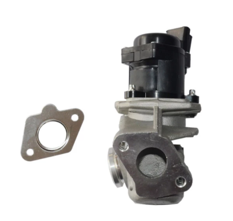
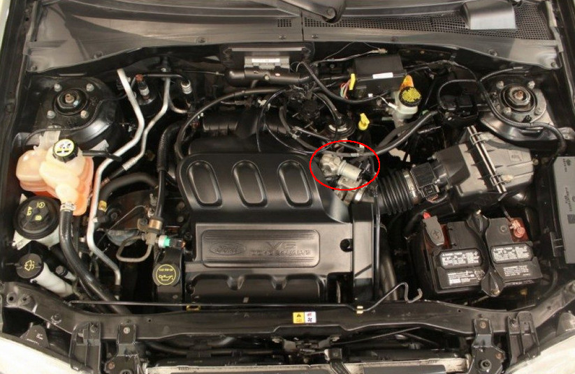
The idle control actuator is a bypass valve consisting of a closed moulded housing with a servo-assisted flanged valve unit to which a nozzle holder is attached. It releases different air cross-sections by moving the servo unit, thus controlling the air mass flow when the throttle is closed.
The following paragraph may appear a bit technical for beginners, but this is how things are. Let’s see closer below:
The idle speed actuator is used to control the engine speed as part of the overall idle speed control of the engine management system. If the engine’s load status changes unexpectedly during idle (for example, if the air conditioning is turned on, or if you’re driving off-road in first gear, or if any other air and fuel component is required to keep the engine running), the solenoid valve is activated to achieve a higher airflow if the engine speed falls below a critical value which is stored as a constant in the ECU memory. At the same time, the opening time of the injectors is extended and adapted to the engine’s needs.
2. SYMPTOMS OF A DEFECTIVE IDLE SPEED controller: SYMPTOMS
A defective idle speed actuator can manifest itself as follows:
- Variable idle speed;
- Engine stalling at idle speed;
- Engine stalling at idle speed and switching on other dashboard indicators;
- Illumination of the engine light/beeping sound.
3. CAUSES FOR A DEFECTIVE IDLE SPEED controller: CAUSE OF FAILURE

The causes of the failure of the idle speed actuator include:
- Dirt/resinification
- Short circuit in the coil
- Blockage of the electromagnetic drive
- No voltage supply to the engine management computer
4. CHECKING THE IDLING ACTUATOR: TROUBLESHOOTING
When troubleshooting, it is necessary to consider the following check steps:
Step 1. Check the supply voltage
Check the supply voltage when the ignition is switched on.
Measured value: 11 – 14 V.
Note:
Only carry out an ohmic measurement in the de-energized state (connection disconnected).
Step 2. Measuring the coil resistance
Measure the coil resistance with the multimeter between the two connection pins of the idle actuator.
Setpoint: approx. 10 Ohm (observe manufacturer’s specifications).
Step 3. Check the coil for a short circuit in the winding
Check the coil for a short winding circuit between the connection pins.
Measured value in case of short circuit = 0 Ohm.
Step 4. Check coil for winding breakage
Check the coil for winding breakage between the connection pins.
Measured value in case of break = >30 MOhm.
Step 5. Check coil for a short circuit to ground
Check the coil for a short circuit to ground – between pin 1 and the component housing and between pin 2 and the component housing.
Measured value with intact coil = >30 MOhm.
Step 6. Mechanical check
Unscrew the servo unit from the housing. Visual check whether the bypass opens and closes when the valve stem is actuated.
Step 7. Read the fault code
Read the fault code.
INSTALLATION INSTRUCTIONS
Before mounting the idle actuator, clean the bearing surface and replace the flange gasket if necessary.
- Observe the tightening torque!
- Fastening screws 12 – 15 Nm.
Please observe the instructions of the vehicle manufacturer in this context.


